


Simulator of the Rail Interlocking Devices
Highlights
In 2017, our regular customer, a major player in the rail market, asked us to create a set of tools for their microprocessor-based controller that manages all interlocking control functions. The first tool in this product line was a Simulator of rail interlocking operations. The need for this tool was due to complex and time-consuming on-site commissioning processes. These processes can be simplified if executed during testing offsite.
Challenge
Project Challenge
Eliminate some onsite testing while debugging interlocking equipment to reduce risk of signaling failures after commissioning of the rail line.
Customer Challenge
Create a tool for testing interlocking solutions in an office environment.
Solution
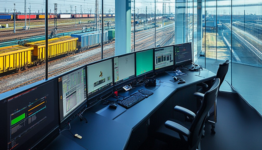
The PSA team developed a railway signaling solution imitating interlocking wayside controllers’ behavior within various signaling scenarios. This allows for testing of how the interlocking operations are executed on a specific rail location. The Simulator operates with applications for real wayside interlocking controllers, as well as interfaces with field devices. The tool can replicate the entire procedure for interlocking actions when a trigger appears, such as the signal’s turning or lowering the crossing barriers.
The tool allows for setup and simulation of vital interlocking components:
-
Field devices – gates, switches, trip stops, signals, track circuits, etc.
-
Customer-specific proprietary and open-source communication links – PEER, SafeP, Modbus, DigiSafe, and a few others.
New components can be added to the tool per request when it is required for a specific rail line. The Simulator can run several applications simultaneously if the location contains a large number of field devices.
The user has the following options:
-
Set pictures for each of the relay types
-
Selective observation of each group of field devices
-
Live display of the log messages
-
Simultaneously view the visualized schemas and bits tables
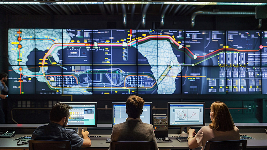
It gives the user a convenient way to monitor every field device as well as the operation of an interlocking system as a whole, and then identify points of failure.
Thus, every wayside device and signaling scenario can be simulated and tested before commissioning on a specific location or during service without access to the interlocking controller.
Also, the Simulator environment is integrated with the Designer environment to test interlocking solutions (applications) once they are developed. To allow visual control of the simulation process, the Simulator can communicate with the Control Client.
Development Included
- Requirements definition
- Architecture design
- Software development
- UI development
- Writing technical documentation
- Product testing
- User manuals and video tutorials creation
- Support activities
Result
-
Need for access to the interlocking equipment for testing was eliminated
-
Commissioning activities have accelerated by 30%
-
Signaling failures have been reduced by 20%
Technology Breakdown
- 1 Technical Coordinator
- 5 Software Engineers
- 2 QA Engineers
- 1 Project Manager
- 1 Technical Writer
- 1 Graphic Designer
- From May 2017