


Application Designer for the Rail Interlocking Control
Highlights
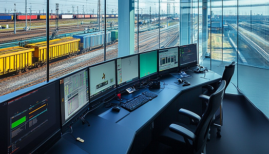
In 2017, our regular customer, a major player in the rail market, asked us to create a set of tools for their microprocessor-based controller that manages all interlocking control functions. Starting from the Simulator, we moved on to develop the Designer suite of applications to execute interlocking operations. The need was due to the complicated manual development of specific applications for interlocking functions, which significantly slowed down the customer's delivery process and raised the possibility of human error.
Challenge
Customer Challenge
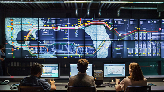
Accelerate the integration of signaling projects into main rail projects.
Project Challenge
Create a solution to simplify and speed up the development of applications to execute rail interlocking operations.
Solution
The PSA team has created a rail signaling solution in the form of the tool for the design and development of applications that enable interlocking functions at a rail location. Applications are source code files of a board-specific language for implementing execution logic, which become files of a special format after compilation and are freely uploaded into and executed by microprocessor-based interlocking controllers.
How the tool facilitates programming:
-
Checks errors and underlines syntactically incorrect code
-
Displays source code in different colors and fonts according to the category of terms
-
Allows re-use of templates with code blocks for different objects of the same type within the projects
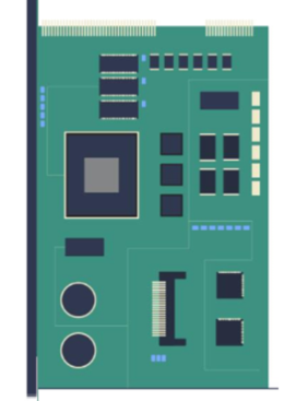
For the programmers who haven’t worked with rail interlocking controllers before, we have provided visualization of the following:
-
Relay equivalent circuits
-
The hardware architecture
Thus, users can see the switches, coils, and bits associated with any application file, as well as create a visual image of the interlocking controllers. This also allows the creation of applications not by writing code but by using visual tools, which significantly reduces time spent.
As a result, the tool is used both by our engineers to continue delivering interlocking solutions for the customer, and by all the developers who create interlocking solutions using our customer’s equipment.
Development Included
- Requirements definition
- Architecture design
- Software development
- UI development
- Writing technical documentation
- Product testing
- User manuals and video tutorials creation
- Support activities
Result
-
The delivery of interlocking solutions has accelerated by 50%
-
Human errors in the design are eliminated
Technology Breakdown
Further Cooperation
The Designer environment is expected to integrate with the Simulator environment to test interlocking solutions (applications) once they are developed.