


Interlocking Systems for Commuter Rail
Highlights
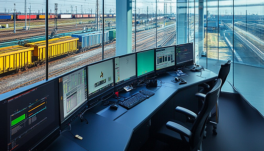
In 2018, we were contacted by our regular customer who is a major player in the rail market. Having ten years of successful delivery of railway signaling solutions to the client, we were entrusted us with another global project – upgrading the interlocking system for a major commuter rail. PSA’s scope included interlockings that should operate on their specialized equipment. The overall project consists of 5 lines and 2 branches, and as of 2022 we have successfully completed work on 4 lines and 1 branch.
Challenge
Customer’s Challenge
Being a global player, the customer is always in the public eye. In order to support their reputation on the market, it is critical to avoid incidents, dangerous cases, and missed deadlines. Having a large number of subcontractors, they need to provide robust connections between them in order to be consistent at every stage of the project.
Project Challenges
All the requirements on the project come from technical specifications, property requirements, and federal standards and rules for rail. However, at the beginning of the project, not all subcontractors could provide their parts of the project. This made it difficult to estimate the required equipment, schedule, and scope of work.
The PSA team needed to communicate with 5+ other client subcontractors simultaneously, while considering the terms of every involved party. The need to coordinate plans with all subcontractors on the project, as well as the large amount of documentation, created some challenges:
- Difficulty in long-term planning due to delays connected to some other subcontractors.
- The presence of outdated technical documentation, like existing drawings not corresponding to the actual situation on the field.
- Due to the possible inconsistency of the documentation, our engineers would likely have to go out to the field for a detailed survey of the current situation.
- Сoordination of adopted technical solutions with the customer might take a long time.
- The customer decided not to use certain equipment in the new project and communicated this decision very late, which forced us to revise deadlines and redo work that had already been done.
Thus, our team had to be flexible and adjust to a changeable environment, accurately notice inconsistencies between drawings and photos from the object and reality, and take responsibility for correcting mistakes from other participating parties.
Solution
To complete the modernization project, we provided the client with project documentation, software development, and testing at the factory and in the field, in the presence of customer representatives.
At the stage of the documentation survey, we detected that the control lines displaying the track development, routes, the presence of coding, aspects of coding and signals were not fully developed. This led to frequent changes in both hardware and software design. Here we encountered the following problems:
- Dismantled equipment and cables were not deleted from the drawings;
- Some equipment that was retrofitted was not listed in the existing drawings;
- The drawings of the relay circuits did not correspond to the real ones, and contacts were missed;
- The switch control and indication circuits did not correspond to the actual used type of switch machine;
- A need of changing the type of enclosure for equipment; for example, a house was replaced with several cases;
- The customer moved or dismantled the insulating joint and did not tell us about it.
To solve these problems, we did a detailed survey of each interlocking before starting the design. We also made a request to clarify the principle of operation of some circuits. Finding such issues in a timely manner helped to avoid re-ordering or under-ordering of the equipment.
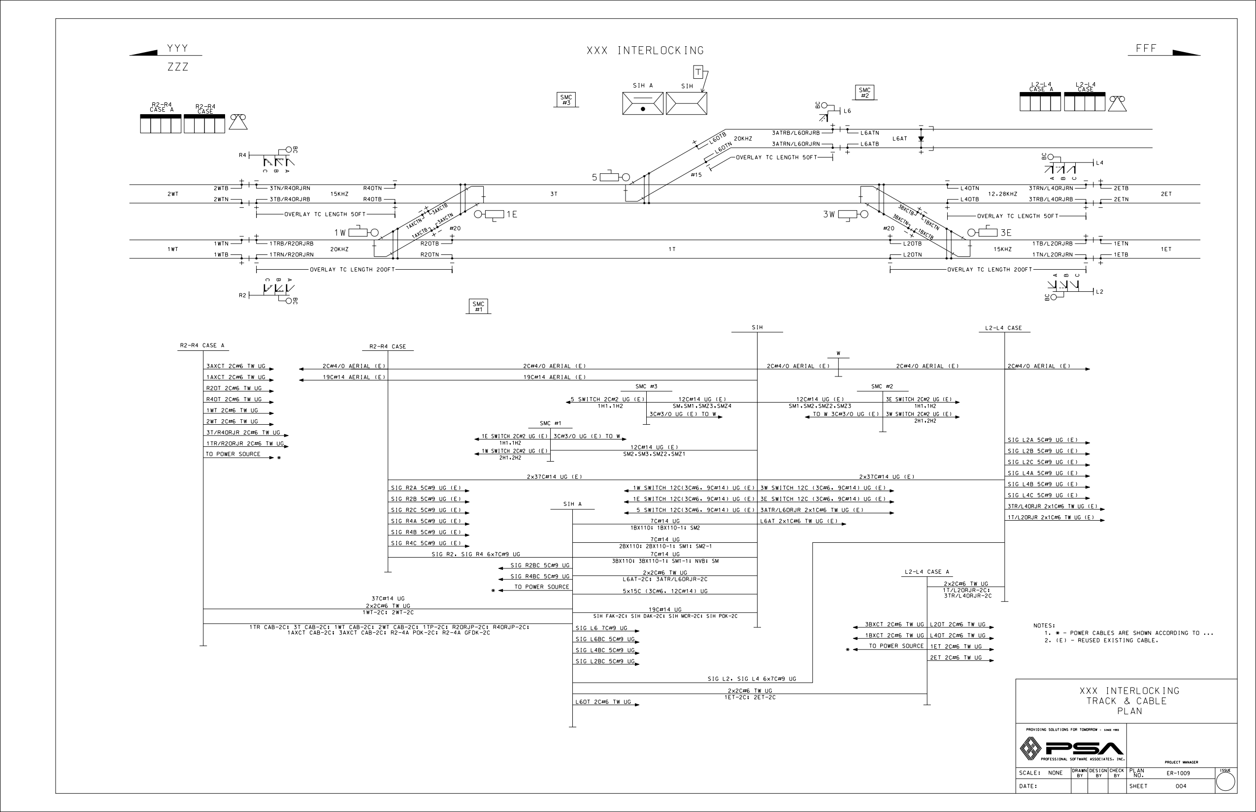
At the state of drawings design, we developed circuit diagrams, wiring diagrams, and layout diagrams – a full cycle of development to describe all connectivity principles and types of equipment, and provide all necessary information to the factory. The pack of drawings on this project consists of:
- Track and cable plan displaying information about the track situation, types of cables, switch machine and enclosures, track circuits length, polarity plan;
- Detailed block diagram showing architecture of the interlocking system;
- Signal aspect chart with downgrade;
- Control charts;
- Track circuits;
- Signal control circuits;
- Switch control and indication circuits;
- Crossing control and gate indication circuits;
- Maintainer and snowmelter circuits;
- Power distribution circuits;
- Vital and Non-Vital IN/OUT boards circuits;
- Other wiring and detail circuits (layout, terminals, power loops, etc.).
In order for the station to work smoothly during the construction and testing phase, we also connected temporary circuits. This allowed us to keep lines open during the cutover stage.
To assemble equipment in the factory, we provided the customer with detailing and wiring diagrams. Our CAD department operated with an Electrical Wiring System that was specific for the customer.
The communication part was devoted to another company, while PSA received communication drawings and corrected mistakes made by another subcontractor. This was possible thanks to some of our engineers who have a corresponding high education degree, which allowed us to perform communication activities as well. We also checked communication equipment for operability after assembly and installation at the factory.
Bridge control and indication
To provide a connection with rail bridges, PSA created special schemes and communication logic. Bridge control and indication circuits were developed and agreed upon with the customer.
Crossing control and indication
On part of the schemes at this stage, we worked closely with another subcontractor, providing them with the necessary information. We developed the other part of the circuits from scratch, providing the software logic for the crossing operation, and either made a new relay circuit or upgraded the existing one.
Software Design
When developing the software, we considered the principles of relay logic operation and added new ones based on new requirements. It was necessary to take into account the specifics of the interlocking architecture chosen by the customer, the features of the operation of new equipment, add CAB coding logic, change the aspect of traffic signals when one of the lamps failed, communication with other locations and features of communication equipment.
After the interlocking configuration was agreed with the customer, we changed:
- The track plan configuration that involves the limit of a large part of the software
- The logic that controls the LCP due to the peculiarities of the equipment and the communication scheme
- The signal lighting and coding due to changes in control lines
To provide compatibility with the old systems, we created specific schemes to connect to these systems.
At all stages of the project, we communicated with the other subcontractors who worked on communication drawings, installation drawings, control lines, adjacent lines, and crossing facilities building activities. Here the PSA team also coped with emerging issues:
- Since the company responsible for crossings still had not provided us with information about the number of inputs, outputs, and equipment age, we used our knowledge to make educated decisions, so as not to slow down the project.
- Since there were suddenly changed servers within communication equipment, we needed to make immediate changes in already prepared documentation.
- Initially, a changing crossing alarm was not reported to us, so we had to accommodate new equipment into drawings, recalculate the battery, and change the charger.
- Agreeing on the use of a different type of interlockings for AC track circuits.
- When it turned out on site that it was impossible to demolish a private parking lot to install a house, we offered to replace them with cases and promptly redid the drawings.
PSA develops full test procedures and datasheets, and supports both Factory Acceptance Testing (FAT) and Site Acceptance Testing (SAT). After complete and thorough testing at the factory, the equipment goes to the field to be installed. PSA then supports the client during field testing. When equipment is connected and tested, the customer reviews and verifies everything under the eye of our onsite signaling engineer. In case there's an issue, PSA helps to resolve it on the spot. Working onsite, our signaling engineers manage various issues. For instance, they:
- fixed an inconsistency of the power loop;
- detected incorrect operation of the switch machine control and indication circuits;
- detected incorrect CAB code aspect in Block and Control Lines;
- corrected bridge control and indication issues;
- found the cause of the lamp driver board burnout;
- found the cause for the lack of interlocking communication of the line, due to incorrect addresses.
After finding the problem, understanding its causes, and correcting it, the engineers made the appropriate corrections to the documentation.
Thus, our team has performed a lot of related work we were not responsible for. Our education and experience have helped the customer avoid headaches that would arise if such issues were noticed too late.
Development Included
- Requirements definition
- Documentation survey
- Making changes to the documentation
- Circuit diagrams design
- Wiring diagrams design
- Layout development
- Power calculations
- Software design
- Simulation testing
- Factory & Field testing
- As-in-service documentation creation
- Сommissioning activities
Result
The client receives tested interlockings, and connections with the other equipment made possible by our drawings. They are provided with all As- in-Service documentation for SW Design and HW Design, allowing for the completion of this part of the project.
Current Stage
The project is currently in progress. We are fully finished with 4 lines and 1 branch, and almost completed with another 2.
Technology Breakdown
To deliver the solution we ulitized the following technologies:
- Bluebeam
- AutoCAD
- Microstation
- MicroLok Simulator
- HMI (SCanvas Editor)
- MicroLok II, track circuits, signal lightings, switch machines, electric locks, switch machine control equipment, relays
- Siemens Safe Train (communication part, track circuits, relay, crossing systems - equipment), Alstom – switch machines, electric lock
- Harmon or GE – track circuits, signal lamps, crossing equipment HXP(4)
- Electrologic – track circuits
- PTMW – enclosures, houses, cases, shelters